I had a bad match problem between 3.5m wire antenna and the TX transmitting 15m.
The solution is a simple pi type manual antenna tuner unit (MTU).
It is applied as the following sketch.
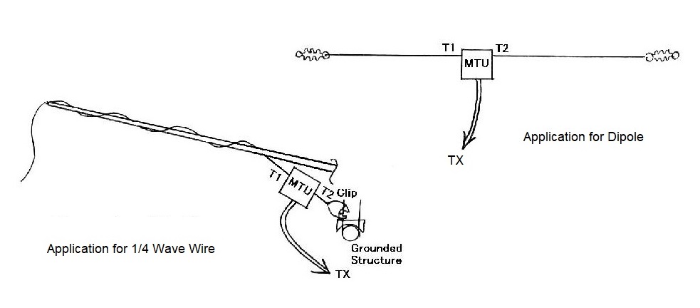
MANUAL ANTENNA TUNER
Antennas should be matched to the TX, and it should be the best to be matched
at the feed point.
I had a bad match problem between 3.5m wire antenna and the TX transmitting
15m.
The solution is a simple pi type manual antenna tuner unit (MTU).
It is applied as the following sketch.
The circuit is quite simple, as shown below, and it works
quite well.
The result is satisfactory,
With MTU
Without MTU
SWR
< 1.1
2.6
Test result on air from Singapore on 21MHz
at 10W his
RST my
RST
JA5DUR/3 54
53
at 50W
BV2UB
57
59
YC1VBH
579
579
HS0ZBS 529
579
4I1P
579 599
It is tested also at 100W. (Thanks 9V1GA!)
What should be careful about is the power
for the tuning of the MTU.
10W for tuning is safe to prevent abnormal
high voltage on VC1 and VC2, which are designed for low voltage.
After it is tuned, it did not have problems at the operations with 50W
and 100W.
However, the acceptable power should be tested by antennas to avoid problems
due to high voltages on the VC's, especially if the SWR of the antenna
itself is higher than 2.6.
For the antennas with extremely high SWR, the power should be 10W or less.
I hope this will be any of your reference.
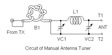
Data of components for 15m Band
B1
7 turn of 1.5D2V coaxial on ferrite triode core with 20mm dia.
Similar core will do with no problm.
VC1, VC2
Poly variable condensers (for radios).
Parallel connected between two channels in each unit.
Desirable capacity : 200pF
L1
14 turns of solenoid coil with 14mm dia and 25mm long (no core)
Originally wound on an UM3 battery.
T1
To be connected to the antenna
T2
To be connected to ground
For 20m Band (for reference)
B1
as above
VC1, VC2
300pF
L1
18 turns of solenoid coil with 14mm dia and 30mm long
(no core)
(Needs
trial)
T1, T2
To be connected to the antenna elements
Note
For balanced types of antennas, it will
be better to put B1 after VC2.
In this case, the circuit will be as follows,
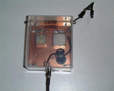
< Petit Revision >
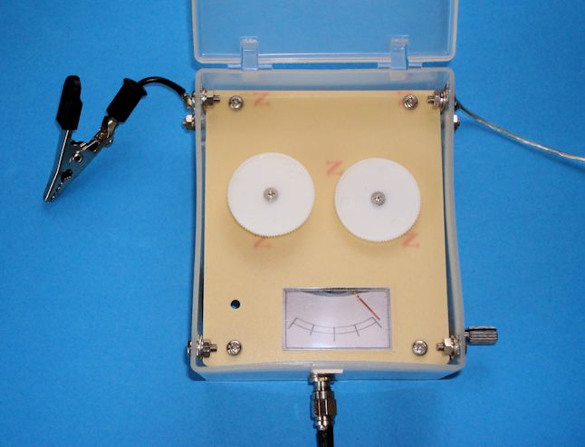
I installed the reflection wave meter in the manual antenna tuner.
After this, the tuner may be tuned without a separate SWR meter.
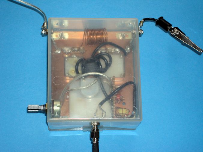
The circuit and the photoes are attached below.
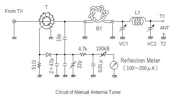
It is just to tune VC1 and VC2 so that the indication of the reflection
meter goes to the minimum.
Data of the transformer T
10 turn coil on the core T-50 #6 or FT-50-61.
For 50W or 100W, use T-68 #6 or FT-82-61.
Be sure that the diode is connected to the same side end of the coil as
the input from the TX.
Previous Page
Home Page